OpenTherm thermostat with ESPHome and Home Assistant
In this series of posts I describe my journey of automating a heating system in my suburban home. This particular post is about a simple, but fully functional thermostat that uses a PID controller to maintain target room temperature. I use this thermostat with OpenTherm-compatible gas boiler, but most of the ESPHome configuration is universal and can be reused with other boilers, if they have a ESPHome component.
In the previous post I left off with a prototype interface board for OpenTherm boiler, which was loosely connected to a ESP32 dev board by a bunch of jumper wires. In this post I am going to build a first useful device using ESPHome and Home Assistant.
Water heating system
It's always good to plan in advance and gather requirements before you heat up the soldering iron. First of all, let's take a look at the system I am dealing with:
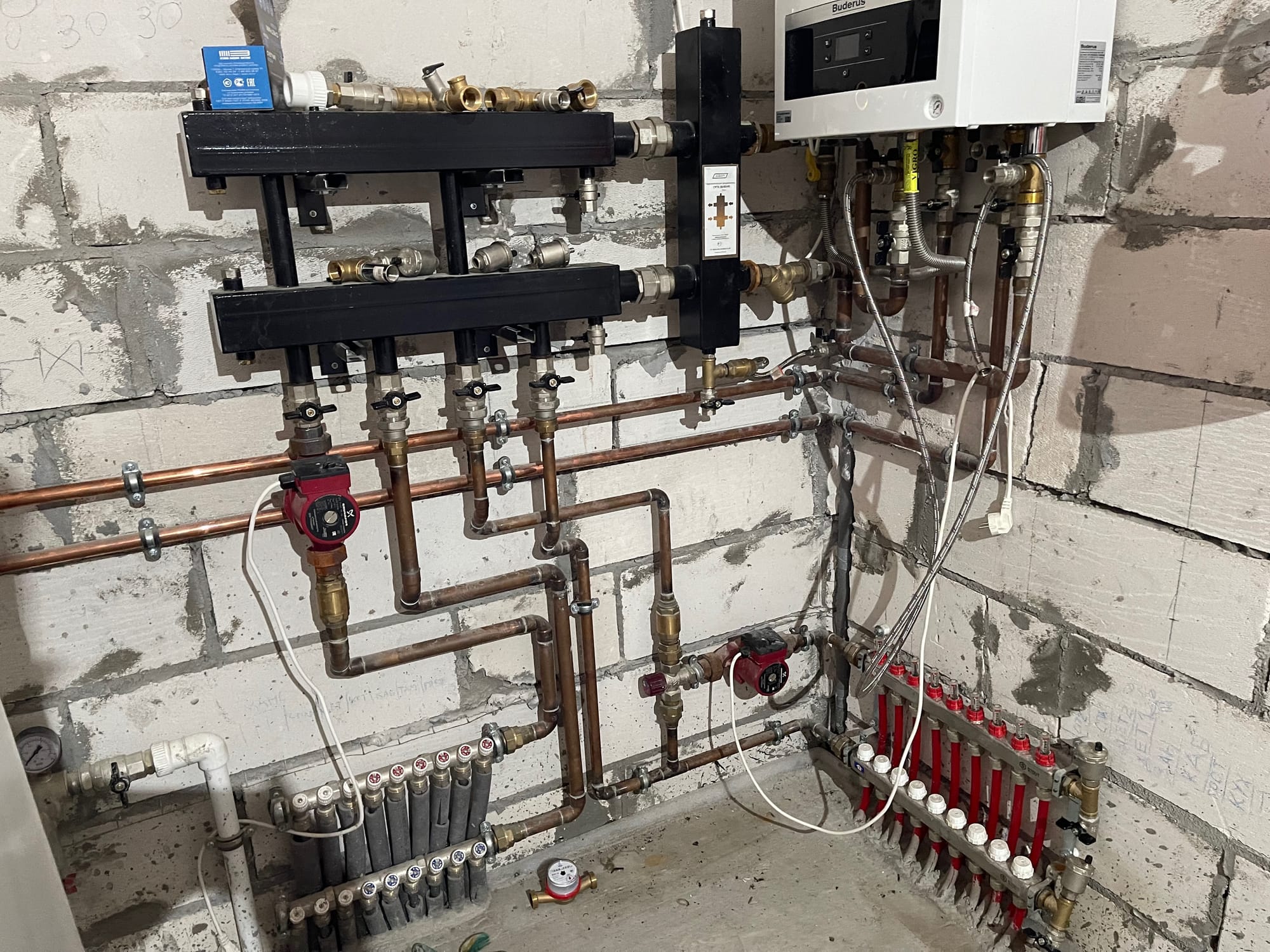
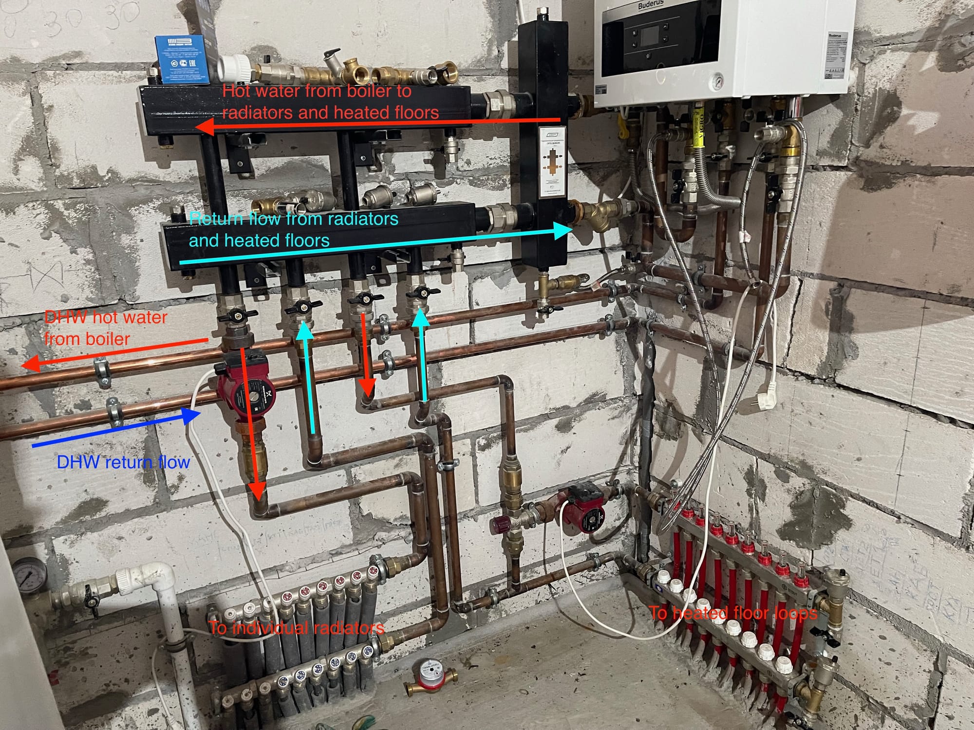
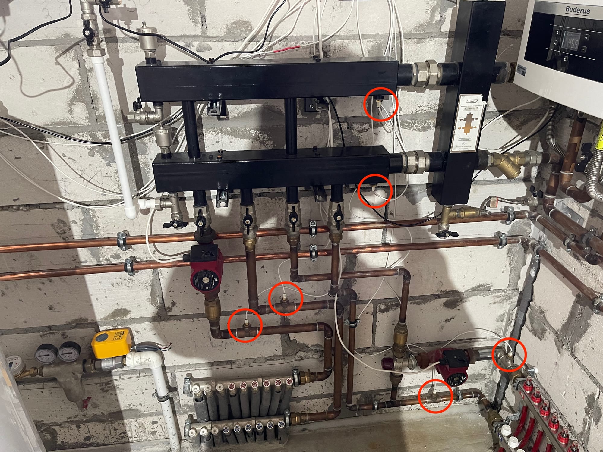
At first glance it looks really intimidating, and it took me a good portion of a week to figure out how it works. I had no prior experience with heating systems, so I had to read up quite a lot of theory before I could make heads or tails of it. It really helps to remember that it's all just water, flowing in the direction of lower pressure 😄
Anyway, here I have 3 subsystems:
- Wall-mounted radiators that do the bulk of heating.
- Heated floor, with one or two individual loops in each room.
- Indirect water heater that prepares domestic hot water for use in showers and faucets.
Radiators and heated floors are merged into one branch, and water heater uses a separate branch. Natural gas boiler can operate only one branch at a time, switching between them when necessary. Hot water for showers and faucets has priority (it's hardwired), so when it becomes colder, the boiler stops heating the house and starts heating the water tank. These two heating branches are closed loops which contain water under pressure of 1.5 atm. So a gas boiler heats up the water in these branches and moves it around the loop with electric pumps. When heated water passes radiators, heated floor pipes or water heater, it transfers its heat, gets colder, and then comes back to the boiler to be heated again. Whew, easy!
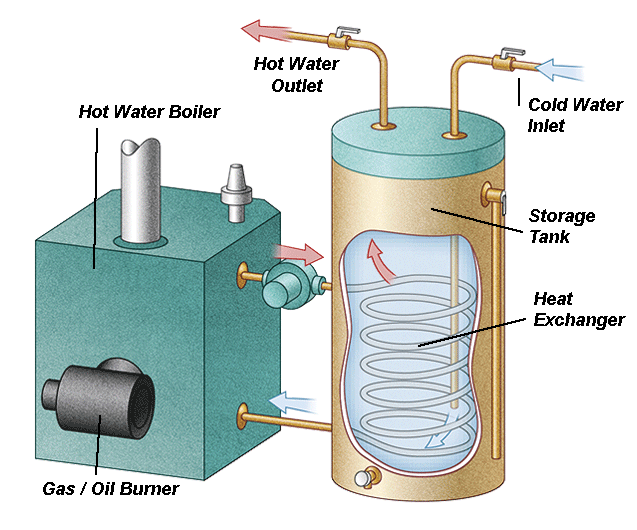
Another branch goes to the indirect water heater that transfers heat from boiler to cold water stored in the tank. This way, faucet water never enters the boiler itself, so that boiler heating loop maintains its own pressure at all times. Here is a simple schematic of how indirect water heater operates:
Boiler control signals
Controlling such a system would seem like a great challenge, but luckily a lot of low-level logic is hidden inside the boiler itself. It turns out, thermostat needs to provide only two control signals to the boiler:
- Central Heating setpoint, which is the temperature of heated water coming out of the boiler in a central heating loop. For example, I can tell the boiler that I want water to be 60° C at all times, and it will control its burning intensity and on-off cycles to match this temperature to the best of its ability. So I would always get water entering my heating system at 60°.
- Domestic Hot Water (DHW) setpoint, which is the temperature of hot water coming out of the water heater to showers and faucets. Since domestic hot water never enters the boiler and heat transfer is happening inside the storage tank, the boiler needs an additional temperature sensor that needs to be placed in a special slot in the water heater. That way boiler knows when hot water stored in the tank becomes cooler and it's time to switch to DHW loop from central heating.
In theory, I could tell the boiler to always support each setpoint temperature constant, and it's usually OK with DHW. But this approach is suboptimal for central heating, especially when weather is not that cold yet. Wall-mounted radiators would run for a short period of time at full capacity, overshoot target room temperature by 1-2 degrees and then turn off for a long time to wait for temperature to drop. This leads to unnecessary temperature fluctuations, which can easily be avoided. In order to control target room temperature more smoothly, I can vary Central Heating setpoint so that radiators and heated floors don't blast with full power, but rather stay just warm enough to support a comfortable room temperature.
Monitoring
It's always a good idea to monitor production systems, and water heating is no exception. There is not much variety in what I can monitor:
- Temperature. Placing temperature sensors strategically can help „debug” heating systems and tune some hard to guess parameters like water pump power.
- Pressure. Maintaining near-constant pressure is critical for a heating system. It's usually achieved by installing expansion tanks, but it's always a good idea to be able to monitor system pressure remotely.
- Various boiler parameters, like whether it's currently burning, or what heating loop is active.
In this prototype I decided to limit monitoring to temperature and boiler parameters, since I wasn't able to find an affordable and reliable digital pressure sensor. In order to monitor temperature, I decided to use widely popular DS18B20 temperature sensor. I like its simplicity and ability to daisy-chain several sensors on a single 1-Wire bus.
Schematics and soldering
It's time to design a schematic for my thermostat. I am using a variation of Wemos D1 Mini ESP32 development boards in this design. You can use any ESP32 dev board that is supported by ESPHome, or even roll with a bare bones ESP32 SoC. I find dev boards exceptionally handy during prototyping phase. I even contemplate using dev boards in my final designs due to their small footprint and ease of soldering. Another perk of using a dev board is on-board USB and voltage conversion support. You can power your whole device with any 5V USB power supply and easily debug it if something goes wrong.
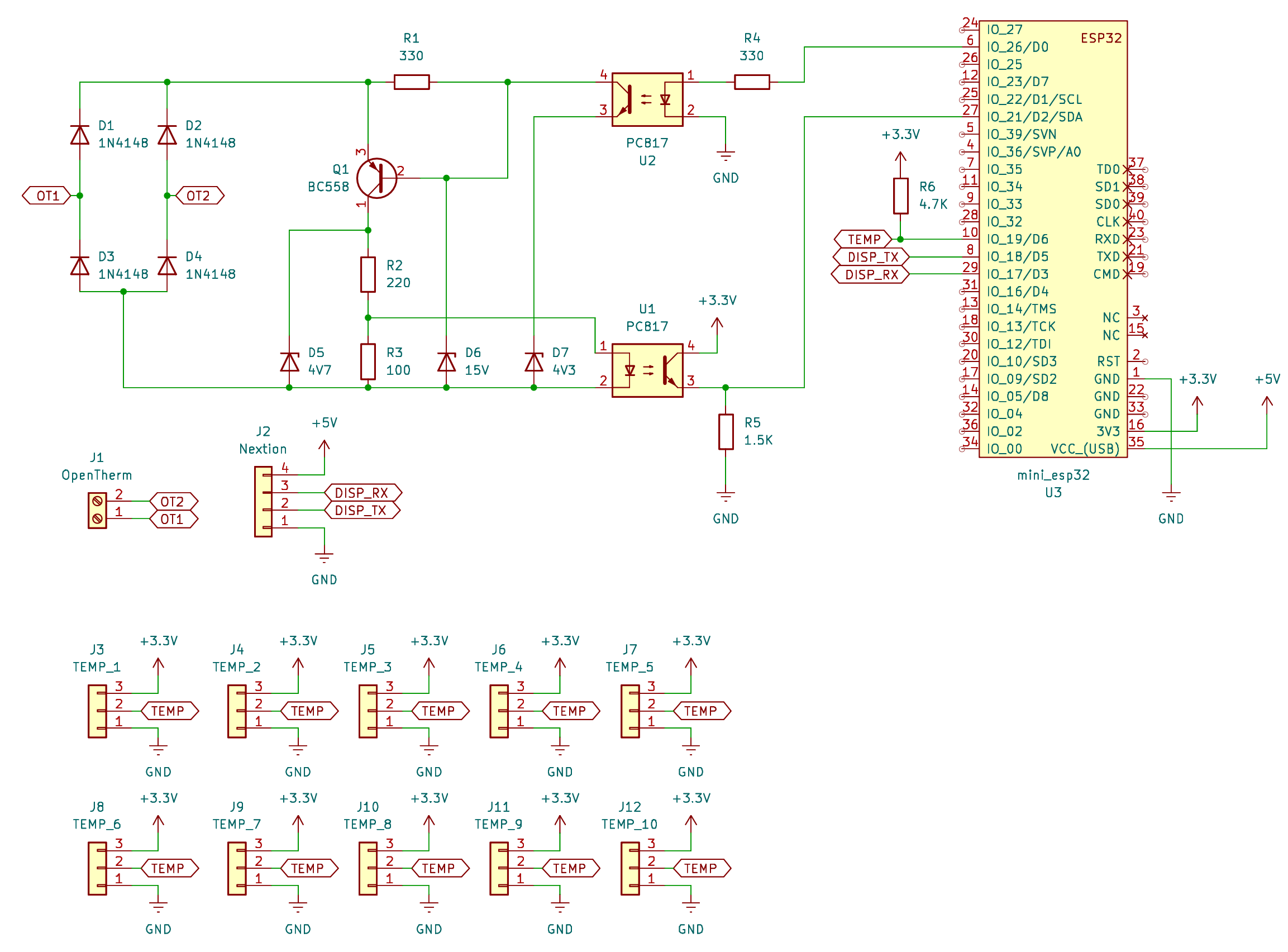
As you can see here, most of the schematic is an implementation of Ihor Melnik's OpenTherm adapter. I also added one 4-pin connector for a Nextion Display (will be covered in one of the next posts) and 10 3-pin connectors for various temperature sensors I plan to install into my system.
Long story short, this is the final prototype PCB:
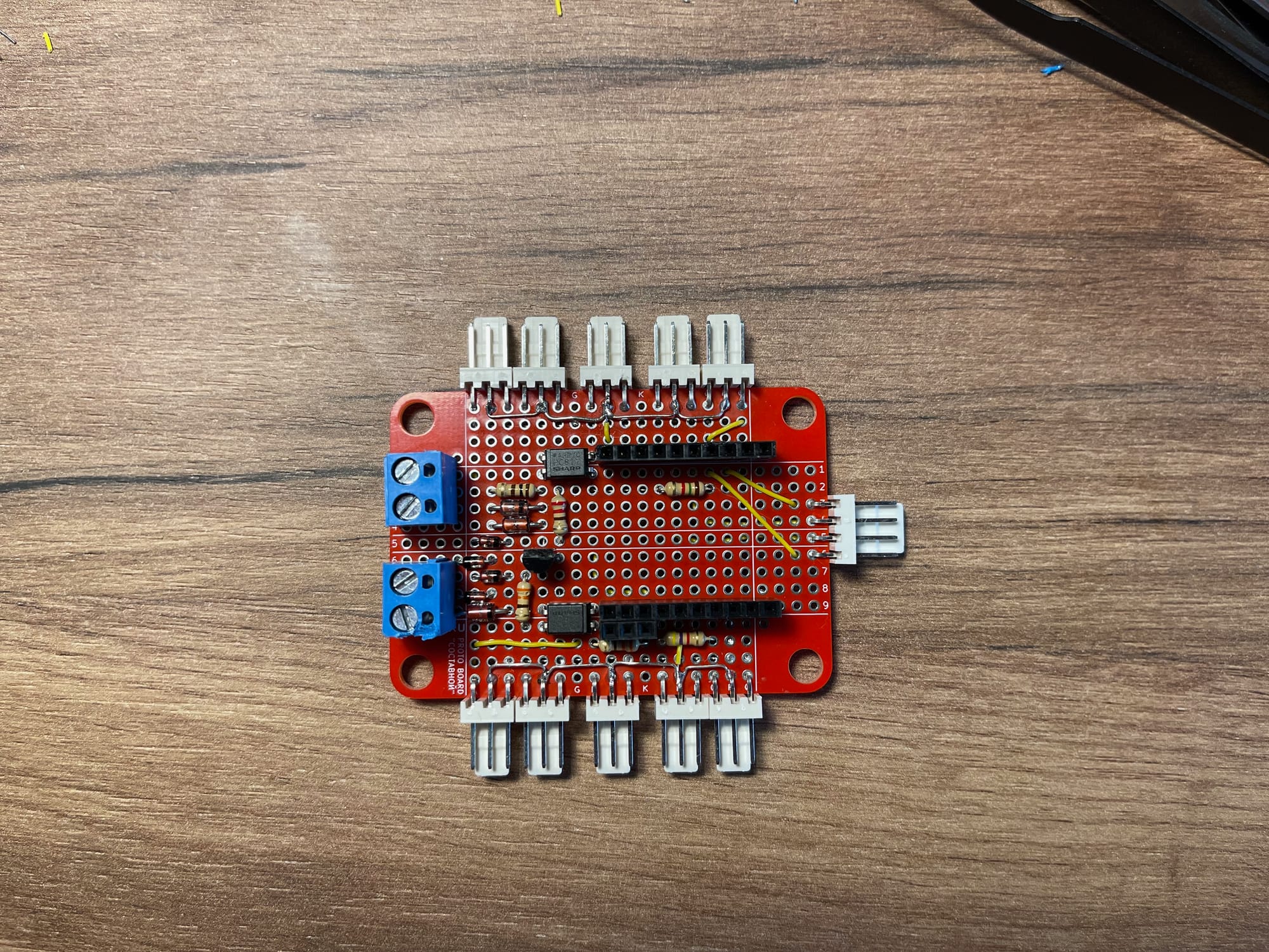
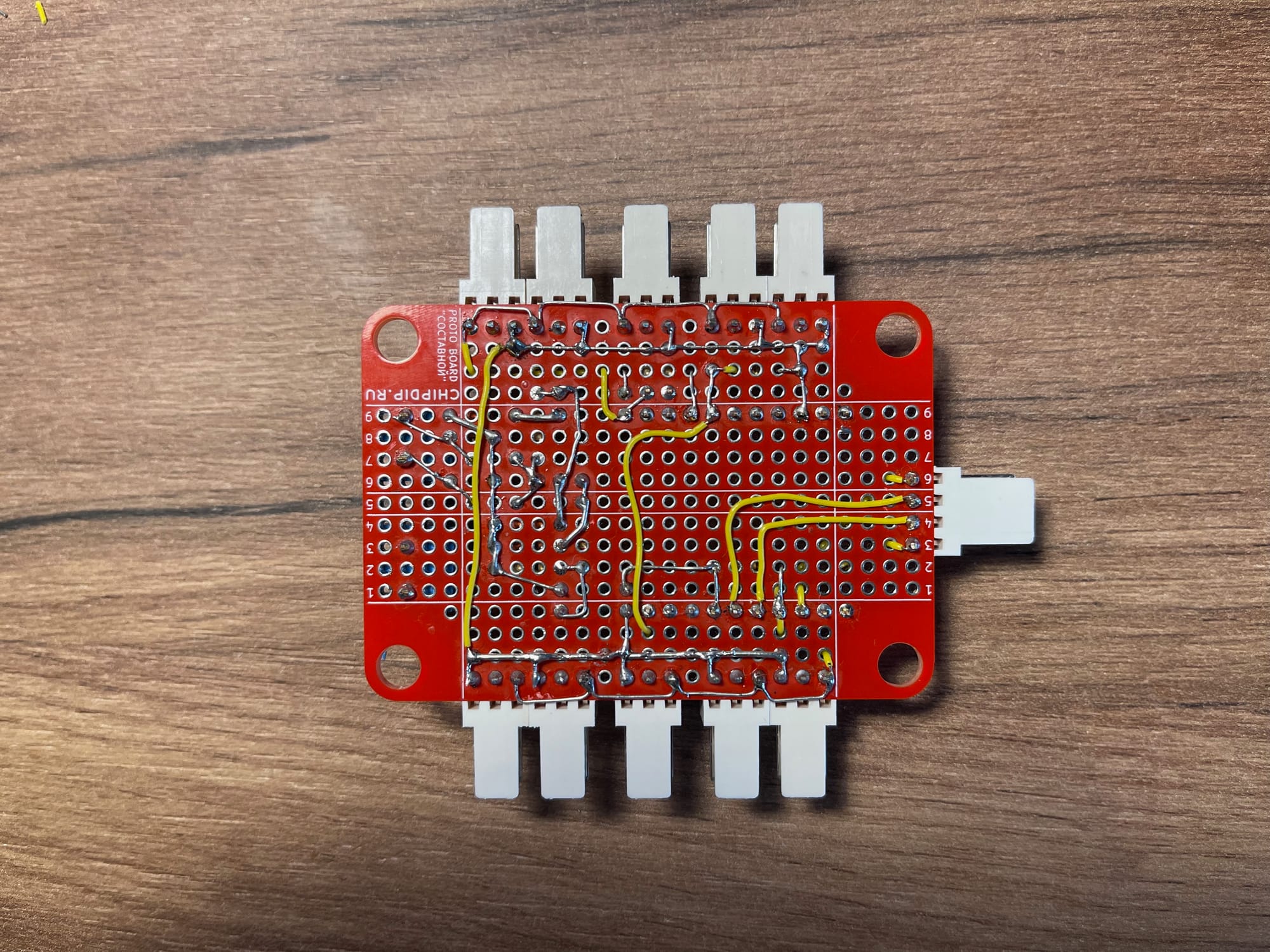
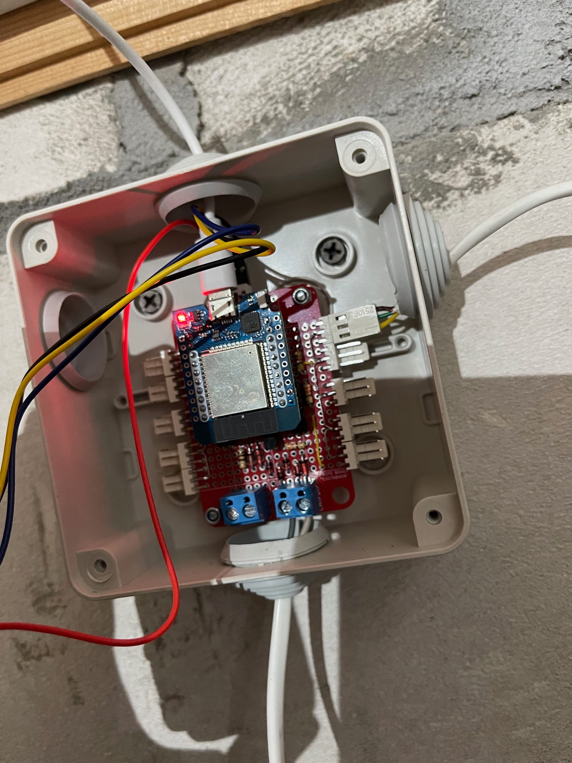
It's definitely not a pinnacle of soldering mastery, but it works 😄 You can notice that there is a second screw terminal that is absent from the schematics. This an additional 5V power terminal that can be used to power the PCB instead of ESP32 board USB connector. I'm not sure whether it will be used in the final design, so I omitted it from the schematics. Here's how it looks in a temporary enclosure with boiler and one temperature sensor connected:
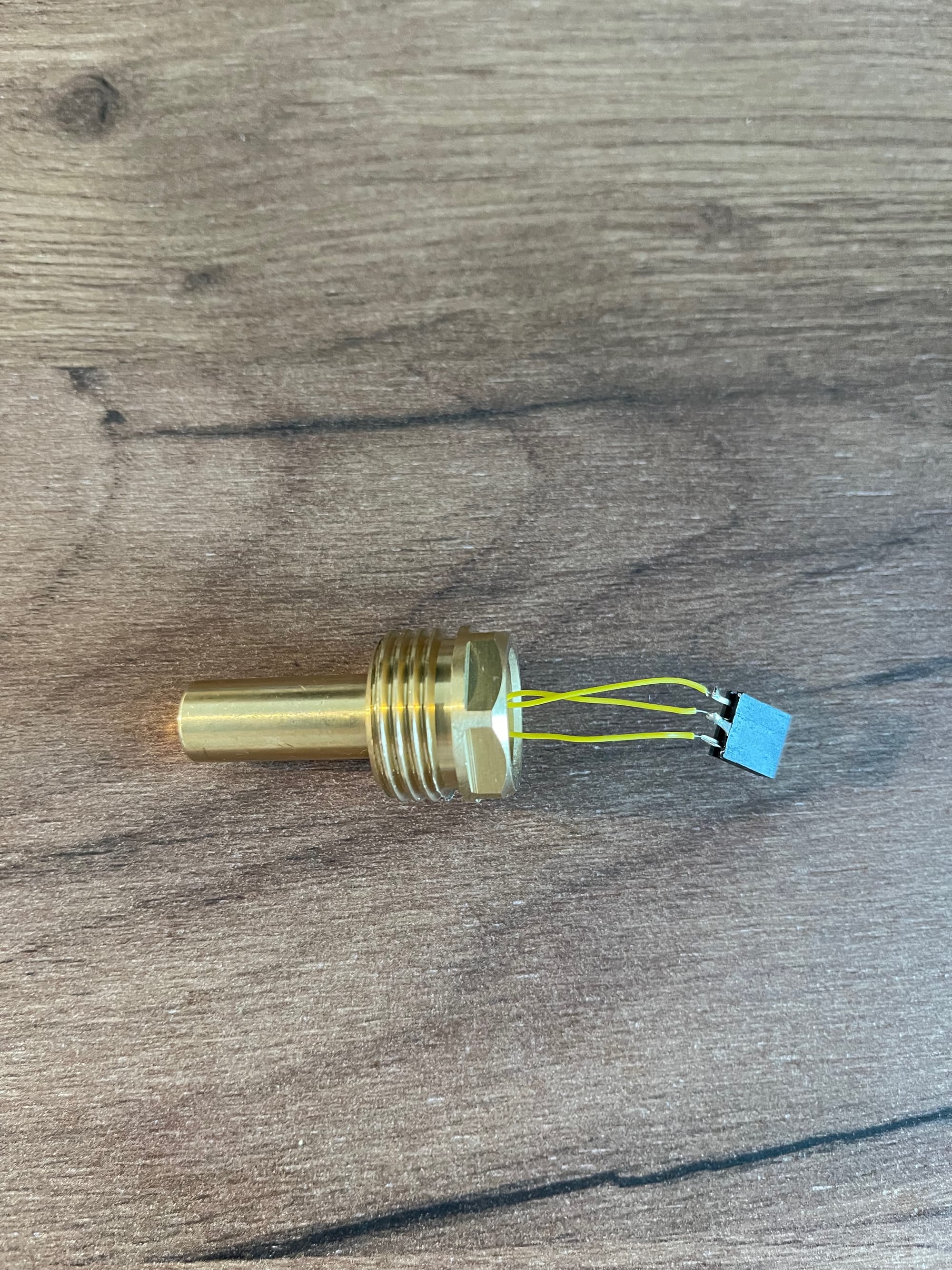
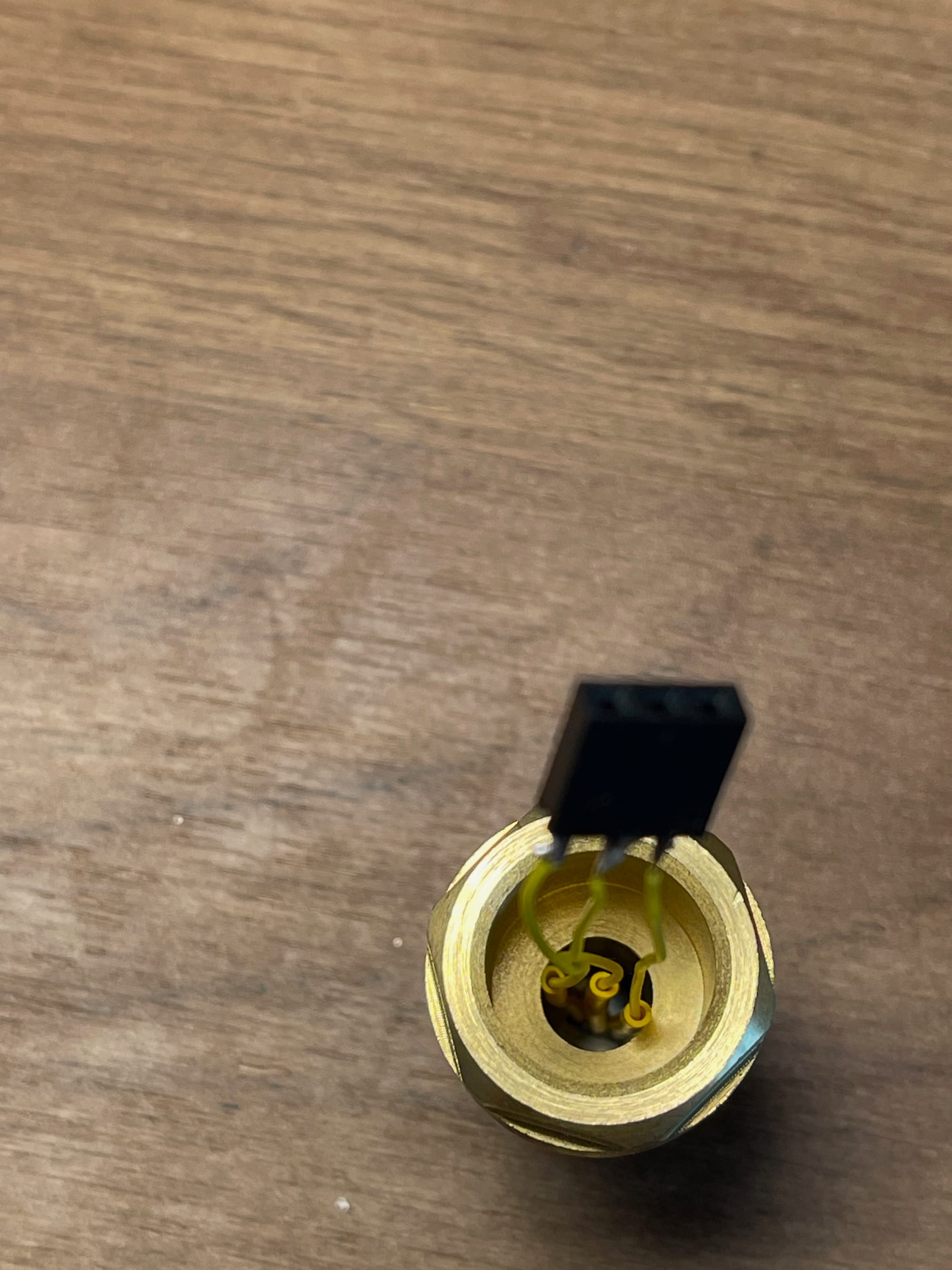
I also made 8 or 9 screw-in temperature sensors to monitor temperature in various point in my system. I bought super cheap analogue gauge thermometers, threw out the thermometers and glued a bunch of DS18B20 sensors into screw-in enclosures. I used a thermal glue which is also used to glue CPU heat sinks, and later filled it all with heat-resistant resin. Here is an individual temperature sensor and the whole rat's nest of wires when they are all connected:
Configuring ESPHome
The final step in this little adventure is configuring and uploading ESPHome firmware to the device. But first we need to install ESPHome.
Installing ESPHome in Home Assistant
The great advantage of ESPHome is its tight integration with Home Assistant. While you can install ESPHome on your machine and don't use HA at all, it's much easier to start with HA integration, if using your device in HA is ultimately your goal.
To install ESPHome in HA, I went to Settings → Add-ons → Add-on store. I found ESPHome in the add-on list and installed it. It's also a good idea to turn on the “Show in sidebar” checkbox in order to find ESPHome dashboard more easily. I am running Home Assistant in its Operating System form, so I'm able to install and maintain add-ons easily. If you are not using HA OS, then you probably can't install ESPHome add-on from the store. Your other option might be installing ESPHome on your machine by following the docs.
Creating a new configuration
Creating a new device in ESPHome dashboard is really easy. I followed the wizard and after a little while ended up with a basic firmware uploaded to my prototype device. After that first upload updating the device is usually performed over the Wi-Fi. If you are not sure about this step, be sure to consult the official docs for the most up-to-date instructions.
In the next few sections I will gradually build up ESPHome configuration to get a minimally functioning thermostat with PID control.
Basic setup
First of all, I declare some basic stuff: dev board configuration, wi-fi credentials and API keys:
esphome:
  name: boilotron
  friendly_name: Boilotron

esp32:
  board: mhetesp32minikit
  framework:
    type: arduino

# Enable logging
logger:
  level: INFO
  logs:
    component: ERROR
    sensor: WARN
    opentherm.output: INFO

# Enable Home Assistant API
api:
  encryption:
    key: "<your key>"

ota:
  - platform: esphome
    password: "<your password>"

wifi:
  ssid: !secret wifi_ssid
password: !secret wifi_passwordYou can still reference it as an external component from my repo in case you want to test some bleeding edge changes that haven't been merged to ESPHome yet.
OpenTherm configuration
Next I declare OpenTherm configuration with its controls and sensors:
# Declare the phisical pins that OpenTherm adapter is connected to
opentherm:
  in_pin: 21
  out_pin: 26

# Outputs are controlled by some other components, not manually
output:
  - platform: opentherm
    t_set:
      id: ch_setpoint
      min_value: 40
      max_value: 60
      zero_means_zero: true

# Values that can be set maually from HA interface
number:
  - platform: opentherm
    t_dhw_set:
      id: dhw_setpoint
      name: "Hot Water target temperature"
      min_value: 20
      max_value: 60
      restore_value: true
      initial_value: 60

# Switches that can be operated manually from HA interface
switch:
  - platform: opentherm
    ch_enable:
      id: ch_enable
      name: "Central Heating enabled"
      restore_mode: RESTORE_DEFAULT_OFF
    dhw_enable:
      id: dhw_enable
      name: "Hot Water enabled"
      restore_mode: RESTORE_DEFAULT_OFF

# Boiler numeric sensors
sensor:
  - platform: opentherm
    rel_mod_level:
      id: rel_mod_level
      name: "Boiler Relative modulation level"
    t_boiler:
      id: ch_temp
      name: "Boiler Feed Temperature"

# Boiler binary (True/False) sensors
binary_sensor:
  - platform: opentherm
    ch_active:
      id: ch_active
      name: "Boiler Central Heating active"
    dhw_active:
      id: dhw_active
      name: "Boiler Hot Water active"
    flame_on:
      id: flame_on
      name: "Boiler Flame on"
    fault_indication:
      id: boiler_fault
      name: "Boiler Fault"
      entity_category: diagnostic
    diagnostic_indication:
      id: boiler_diagnostic
      name: "Boiler Diagnostic"
      entity_category: diagnostic
There is a lot to process here, but let's dissect this config step-by-step. First of all, on the top level you can see components: outputs, numbers, switches etc. These are sometimes confusing, because a component can live on the top level, like opentherm here, but in other cases top-level statements represent component „classes”, with components nested underneath, like switches and sensors. There is no apparent system to this, you just need to consult ESPHome documentation a lot 😃
First of all I'm configuring base OpenTherm hub component to let ESPHome know which pins my adapter is connected to.
Next I declare several components that let me control the boiler and read its state. The most important is t_set component of class output. It corresponds to central heating setpoint, and declaring it as output means that I will not set its value manually, but rather through some other component. In a couple of moments I will connect a software PID controller to this output. There are some additional properties like min and max values. Recommended maximum temperature for heating system with wall-mounted radiators is usually 60° C and minimum temperature needs to be discovered empirically. I found that 40° is the minimum temperature that my boiler can sustain on its lowest burn intensity without turning off and on again.
Note that esphome-opentherm allows to declare any non-sensor component as a number — that way you will be able to set its value manually using Home Assistant UI. This is exactly what happens with t_dhw_set component — as noted earlier, we usually want faucet water to be roughly the same temperature, so I just need to set this temperature once and let boiler handle the rest.
I also declare two switches that allow me turn central heating and DHW on or off completely: ch_enable and dhw_enable. The state of these switches can be restored by ESPHome after reboot and I also prefer to set them to „off” in case no saved value is present. RESTORE_DEFAULT_OFF allows me to do just that.
After that I declare a bunch of sensors that can be read from the boiler. rel_mod_level shows current burn intensity and t_boiler shows the temperature of the water coming out of the boiler (this is the temperature that we set with t_set). There is also a bunch of binary flags that indicate current state of the boiler.
OpenTherm is a common standard with many vendors and boilers implementing it to a different degree. My boiler is one of the simpler ones, and this is all the info that I can get out of it. Other boilers support more sensors, and you can find the whole list in ESPHome documentation.
Adding room temperature sensor
My goal is to maintain a fixed room temperature with minimum variation. In order to do that, I need to get this temperature from somewhere. In my target design I will place climate sensors in every room and connect them all to Home Assistant. It will be a complex control system which will have an ability to control temperature in each room individually with TRVs placed on radiators. But I should also plan for failure and make sure that my heating system can operate on a basic level when Home Assistant and even Wi-Fi are down. It's also impractical to try and build a complex system right off the bat. I better start with something simple, and then iterate to add complexity.
The most self-contained way to measure room temperature that will be resilient to network failure is to connect a temperature sensor to the thermostat itself. So it's time to connect a sensor to one of the temperature connectors that I left on the board and add some more ESPHome configuration (I omitted all the screw-in temperature sensors for the sake of simplicity):
# Temperature sensor hub
one_wire:
  - platform: gpio
    pin: GPIO18

sensor:
  # [.. boiler sensors omitted ..]

  # Temperature sensors
  - platform: dallas_temp
    address: 0x2001229265635128
    name: "Room Temperature"
    id: room_temp
    accuracy_decimals: 2
    update_interval: 30s
    filters:
      - sliding_window_moving_average:
          window_size: 5 # Average over this number of last measurements
          send_every: 2 # When sensor update interval is 30s, new value will be pushed every minute
      # PID controller updates its parameters only on sensor signal, so we push the last value every second
      # We don't want to actually read the sensor temperature every second, since it would hurt performance.
      - heartbeat: 1s
First of all, I declared a one_wire component, which contains pin number for all the temperature sensors that are daisy-chained on a single 1-Wire bus.
Next I setup individual temperature sensors. It's important to note that this configuration goes into the existing sensor section, where I placed some OpenTherm sensors earlier. The most important here is sensor address. You can find out your sensor addresses by temporarily setting logger level to DEBUG and rebooting your device. ESPHome will print out addresses of all found sensors, so in order to determine an individual address you need to connect your sensors one by one and reboot after each new sensor is connected.
I also set update_interval so that all sensors on that bus will be polled once every 30 seconds. I wouldn't recommend decreasing this interval by much, since 1-Wire communication seems to hurt performance and even interfere with OpenTherm protocol (more on this in a separate post).
On top of that I added several filters to this particular sensor. I'm going to use a PID controller to calculate target t_set temperature based on room_temp temperature and there is a couple of considerations here:
- Digital temperature sensors can be rather noisy. For example, you can observe random small changes from one measurement to the next. These are OK when you just print your temperature reading to a dashboard, but for a PID controller every input change is a trigger to adjust the control signal. Such noise doesn't reflect well on the resulting signal, so you typically want to make your temperature readings smoother. That's why I added a
sliding_window_moving_averagefilter which does just that: it takes last 5 measurements, averages them, and reports every other one to ESPHome. So if myupdate_intervalis 30 seconds, every minute I will get a new measurement averaged over last 2.5 minutes. These values are eyeballed empirically and you might need different values based on how your particular sensors behave. - PID controller output is adjusted only when new input value is received. PID controller works by making small changes to current output value, so pushing a new input each minute will be ineffective: we would wait for a very long time for
t_setto change even a little bit. To combat that I apply aheartbeatfilter to my temperature sensor. It remembers last known temperature reading and pushes it out every second. So effectively I will drive my PID controller every second with the same input, and each minute that input has a chance of updating if room temperature actually changes enough to go through the sliding average filter.
I know, all these settings seem a bit arbitrary — that's because they are. Finding the right combination of filters and coefficients took me some time of just running this system and staring at Home Assistant dashboard. If you try to reproduce this design, you might get lucky and these numbers work for you too. If they don't — don't despair, you can probably tune it to your environment in a couple of hours 😃
Adding PID control
OK, this is a super long post already, but bear with me — we are almost there. It's time to put all these things together by adding a PID controller. It will take room temperature as an input and output a single number in range of [0..1], which is then scaled to fit the range of [min_value..max_value] in our t_set component.
The most useful example to help you understand a PID controller is cruise control in a car. You tell the car its desired speed and an onboard computer slowly tunes fuel intake and other parameters to reach that speed over a period of time. It's important to understand that no control system reaches its target instantaneously (you can't accelerate from 0 to 100 in 0 seconds) and it's usually not desirable to change control signals by large amount (you can shift from first to fourth gear, but you car won't thank you).
PID controller is a vital part of large and complex fields of control theory and industrial automation. People actually get degrees in this stuff, and that's exactly what I did more than a decade ago 😀 But the truth is that most of this theoretical apparatus is very rarely used and people are just eyeballing the coefficients, even at serious establishments like oil refineries and nuclear plants. If you want to dive deeper into the theory, I suggest starting at ESPHome documentation for PID controller. It's a good idea to understand how it works in detail, but it's not required right away. You can try my values and see if they make sense in your environment.
Here is how I configure a PID controller:
climate:
  - platform: pid
    id: boiler_pid
    name: "Central heating"
    heat_output: ch_setpoint
    default_target_temperature: 23
    sensor: room_temp
    visual:
      min_temperature: 15
      max_temperature: 30
      temperature_step:
        target_temperature: 0.5
        current_temperature: 0.1
    control_parameters:
      kp: 0.5
      ki: 0.001
      kd: 0 # Derivative term reacts too much to small changes in temperature, effectively turning off the boiler while target temperature is still far
The most important settings are these:
sensor— this is the input that is used to calculate the control signal. I putboilotron_temp_roomthere to point to my temperature sensor.heat_output— the component that I want to control. I putboilotron_ch_setpointthere to controlt_setvalue.default_target_temperature— default temperature that I would like to have in my room. This is a starting point, and I can change target temperature in home Assistant UI later.
There is a visual section that configures how the component will render in Home Assistant UI. I put some sensible boundaries on target temperature and adjust step size.
control_parameters section contains the actual coefficients that are used for PID control algorithm. In ideal world of control theory you would use complicated methods to measure you particular system's response to various control signals, maybe solve a couple of partial differential equations and arrive at perfect values that work for you flawlessly. But in the real world these methods are seldomly used and you can try to reuse my values as they are.
kp and ki values that I got from autotune, and used values 0.5 and 0.001, which look much more straightforward. I now believe that proportional and integral terms alone are enough for home temperature control, and deadbands only add unneeded complexity.The main idea here is that PID regulator outputs lower signal when room temperature is close to target, and higher signal if it's further from target. For example, if my target is 23° and current room temperature is 22.7°, PID controller might output 40°, which is the lower bound in t_set component, heating my radiators just a little bit so that target temperature is reached slowly with little overshoot. But if my current temperature is 19°, the controller will likely output 60° in order to make radiators go full blast and heat the room faster.
Uploading the firmware
After all this was done I compiled and uploaded new firmware to my device wirelessly using the „Install” button in ESPHome dashboard. After a couple of seconds, my device showed up in Home Assistant device list and this is roughly what I see if I open it:
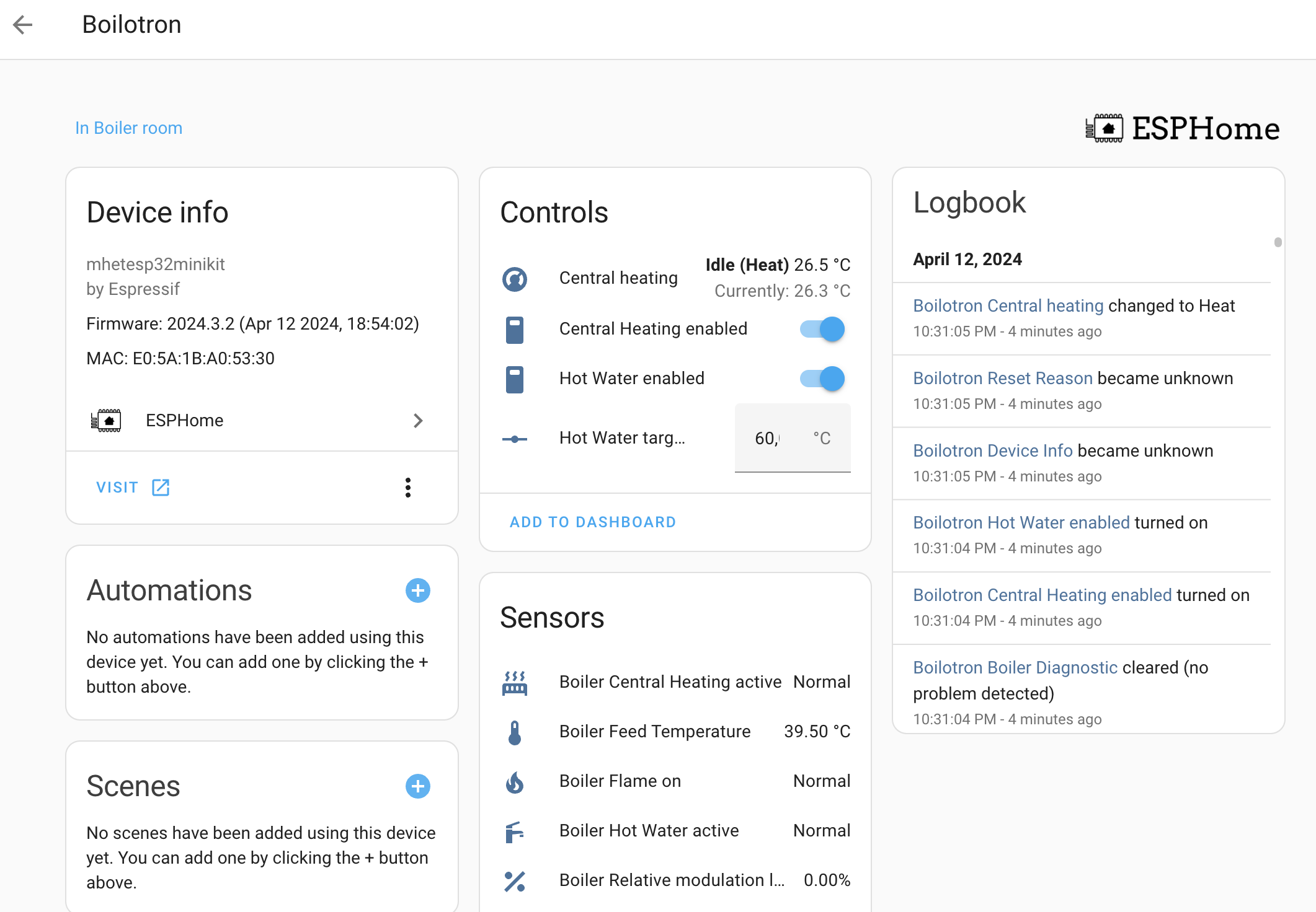
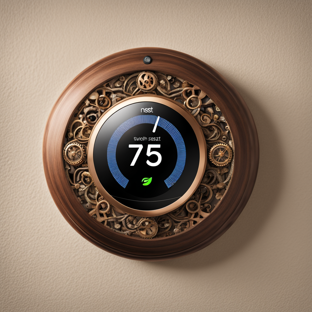
If I click on „Central Heating”, I get a nice Home Assistant thermostat UI:
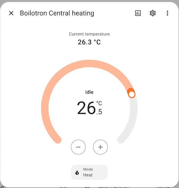
Now I can add some of these items to my dashboard and control my heating system from my phone!
Conclusion
This turned out to be a much larger post than I anticipated. I didn't cover a lot of topics like adding an LCD display or rewriting half of the OpenTherm library. Stay tuned for more posts with hairy details 😃